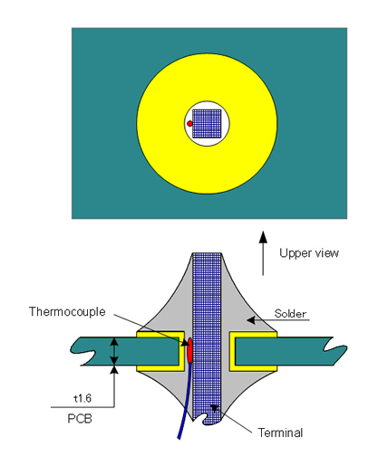
Temperature of through-hole inside became as shown in the profile below (at soldering by PSU500)
Temperature Changes at Soldering Points (profile)
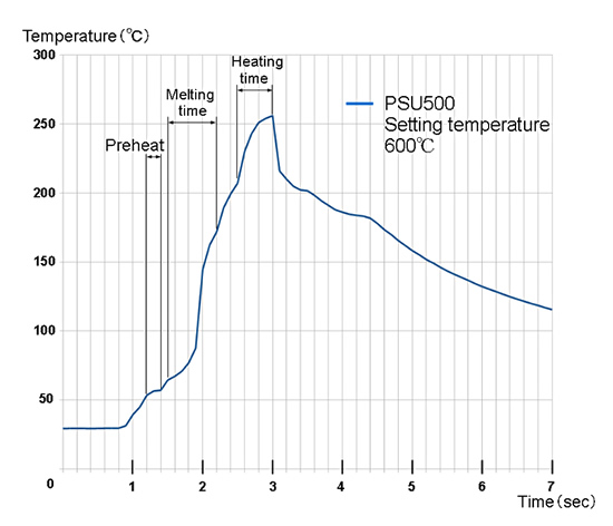


Temperature of through-hole inside became as shown in the profile below (at soldering by PSU500)
Temperature of soldering tip 550°C
Melting time 0.7sec.
Heating time 0.5sec.

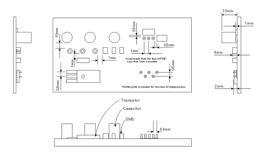
Solderable points and ranges are depending on height and thickness of the terminal and surrounding parts.
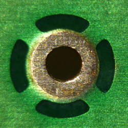
For patterns that has heat loss, making them a thermal relief enables better soldering.

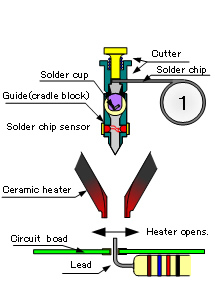
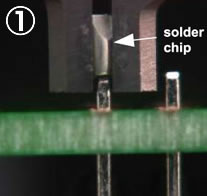
Cutting solder wire with fixed amount
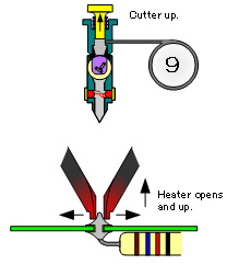
Heater opens
1st down of heater (Heater will stop at the position where not touching to PCB)
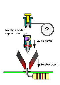
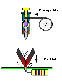
Solder guide down (for supplying Solder)
* For ground pattern, thermal relief point, have a time for preheating before solder guide going down
Heater closed (Melting time starts)
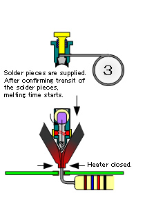
Solder charged
Solder melts
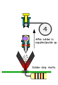
Solder guide up
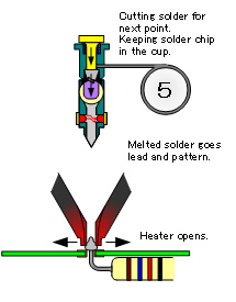
The next piece of solder is cut
Opening heater and melted solder goes lead of parts,
solder will spread out with wetting.
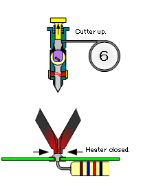
Heater closed
2nd down of heater
* Closing or touching to PCB (setting is available)
Start for heating solder and the work
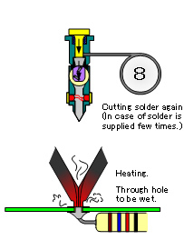
heating
(for wetting more)
Stop heating
Heater opens and up
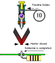
Soldering is completed

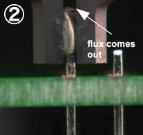
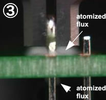
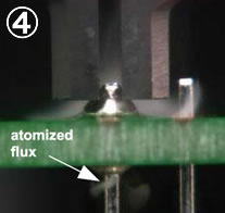
*Atomized stuff flying from heater is activator in flux. Flux atomized in a instant by high temperature, it becomes very fine particle and will be applied to the PCB and lead.
As described above, heat-retaining solder is properly wetted and extended to the place after atomized flux applied, like this, ideal soldering is done.